This is in continuation of the series of blogs where we will be covering some of common development tools used for Bluetooth smart applications. In this part, I will be describing the popular Bluetooth LE SDK from Cypress Semiconductors.
Frequently used terms
In order to explore BLE stack in depth, we wanted to develop a small system demonstrating BLE in action and then build upon it to cover variety of use cases. Before we describe our use case we should first mention the terminology that will be used in this document
BLE Peripheral: A BLE enabled device which will act as a server. This device has the broadcasting/advertising capability. It can both send and receive data to other BLE central device, however it cannot make connection to BLE central device, it can only respond to BLE connection request from other central devices.
BLE Central: A BLE enabled device which can connect to a peripheral device. It can scan the nearby peripheral devices and can make a BLE connection if it wants to send/receive data from peripheral device.
Profile: Bluetooth profiles are definitions of possible applications and specify general behaviours that Bluetooth enabled devices use to communicate with other Bluetooth devices. All BLE enabled devices are implemented with profiles. A Profile is a BLE word for a Bluetooth SIG specified collection of data and functionality which are called services. Example of pre-defined profile are Alert Notification, Heart Rate monitors. It is also possible to create a custom profile using some existing or custom services. In this document we will be using the standard BLE proximity profile to identify the link loss between peripheral and central and also add a custom service to exchange some data over BLE connection
Service: Services are collections of characteristics and relationships to other services that encapsulate the behaviour of part of a device. A service is quite simply the thing that a device can do. For example a device which implements the standard LinkLoss service will have a way of knowing when a connected device either goes out of range or simply terminate the connection. In this case we will be implementing the Link Loss service in the BLE module to identify when the device gets disconnected and take some action. We will also implement a custom service to exchange data over the BLE connection.
Characteristic: Characteristics are defined attribute types that contain a single logical value. A characteristic is all of the information that can be shared across the services. In our case we will use the AlertLevel characteristic to decide what action to take on BLE link loss. Also we will add a custom characteristic through which data can be transmitted over when in connected mode.
Tx: Transmission line or the line from which data is transmitted from the device
Rx: Receiver line or the line from which data is received on the device
UART: Universal Asynchronous Receiver Transmitter. The hardware component used to communicate data (usually in the form of bytes) serially in asynchronous way
Use Case description
The use case that we have developed deals with displaying the state of a BLE peripheral device as and when some central device connects, disconnects and sends data over the BLE channel.
There will a BLE peripheral device which will be in advertising mode. This device will be connected to an LCD display device which will display the current state of the device. If the device is not connected to any other BLE device, then LCD will display “Advertising…” Once a central device X connects to the device, the LCD should display “Device X connected”. When X is connected to the peripheral it can send some data over the BLE channel which should also be displayed on the LCD. Once X goes out of range the display should read “Device X disconnected” for around 20 seconds after which it should again display “Advertising…” and wait for connection to other central devices.
We are going to use BLE pioneer kit by Cypress semiconductors to implement this use case
Hardware Components
- BLE Pioneer baseboard
- CY8CKIT-142 PSoC 4 BLE module: This is the device which will act as our BLE peripheral device. The firmware of this device can be updated using PSoC creator IDE (short for Programmable System on Chip) and BLE Pioneer baseboard on top which the BLE module can be directly mounted on.
- Arduino LCD Keypad Shield: This is the display device which will be used to display current status of the BLE module.
- Arduino Uno: This will be used as an integrator board. It will take the output from the BLE module and display it on the LCD shield
- Breadboard: This will be used to make some external circuit between BLE module, Arduino and LCD shield
- BLE enabled mobile phone with BLE scanner app installed: This will be used as the BLE central device to initiate the connection and send data to be displayed on LCD
Tools/SDK
- PSoC Creator: IDE for firmware design, development, debugging and deployment on PSoC BLE module
- BLE library which comes with PSoC Creator
- Arduino IDE: IDE used for firmware development and deployment on Arduino Uno
- Liquid Crystal library: Library used to program Arduino to work with LCD display
Hardware Connections
System Details
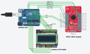
The BLE module has a firmware running a custom profile consisting of two services viz. Link Loss service which will enable it to take some action when the client (or central) goes out of range and a Custom Service which will let the client to send/receive some data. The BLE module is powered through the Arduino board (3.3 V and GND). Three of the output pins of the BLE module(3.6, 3.7 and 2.6) are used to map the three states of the module i.e. Advertising, Connected and Disconnected (PS: We can use just 2 pins to map three states, but for the sake of simplicity we have used three pins for the development). These pins are given to Arduino as input by which the firmware running on it will display the states on the LCD shield. When in connected state the client can send some data on the custom service of the module which can then be transmitted to Arduino through UART channel. For this the Tx and Rx pin of BLE module (1.5 and 1.4) are connected to Rx and Tx pin of Arduino (0 and 1). The firmware running on Arduino will also display this data on the LCD shield.
Setup (BLE module)
- Configure BLE module: As mentioned above we are using PSoC Creator IDE for programming the BLE module. We will modify the existing BLE_Proximity profile
- Create a new Project using New Project wizard. In the select Design Project option, select target device as PSoC 4200 BLE
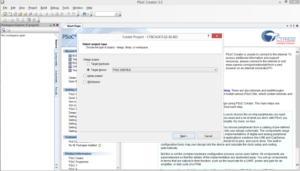
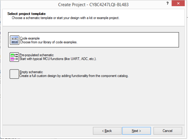
2. In the select project template dialog, select Code example since we will be modifying the existing Proximity profile.
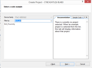
3. In the next dialog box, type “BLE_Proximity” in the filter and select the matching option.
4.Give suitable name to the project and workspace and click Finish.
5. Double click on the Bluetooth Smart component in the TopDesign.cycsh file to configure the Proximity Profile for our application
- Link Loss service: This service will be already present in the Proximity Profile tab. It will have a characteristic called AlertLevel which can be updated by the client to be one of the three values namely ‘No Alert’, ’Mid Alert’ and ’High Alert’. The application logic to be performed based on the value of this characteristics will be explained shortly.
- Custom Service: Add this as a new service under Proximity profile. By default a custom characteristic will be present under the service. Since the client will be sending data for this characteristics as a text, we need to change the data type of this characteristic from default unit8 to uint8 array. By default this property will have Read and Write enabled. This tells the client what it can do with the characteristic.
6. Open the .cydwr file and update the LED name and the pin assignment to the respective. Refer to the circuit diagram above for different pin numbers. By default the Rx and Tx pin will be numbered as P1.4 and P1.5 respectively. We will keep it unchanged
2. Generate code: Once we click on Generate Application (under Build menu option), all the required code for different components of our system will be automatically generated.
- main.c : this is the main application file. For most of the embedded programs there are two main parts of the program
- setup() – All the initialization of different components like BLE module, application callback registration are handled here
- loop() – This is the main loop of the application where the application waits for an event to occur and process the events accordingly.
- Here also we have the similar structure of the program where in the first part we have the initialization code and then a while loop which waits for events and process them
int main()
{
CYBLE_API_RESULT_T apiResult;
CYBLE_BLESS_PWR_IN_DB_T txPower;
int8 intTxPowerLevel;
CyGlobalIntEnable;
/* Turn off all of the LEDs */
Disconnect_LED_Write(LED_OFF);
Advertising_LED_Write(LED_OFF);
Alert_LED_Write(LED_OFF);
/* Start CYBLE component and register generic event handler */
CyBle_Start(AppCallBack);
while(1)
{
/* CyBle_ProcessEvents() allows BLE stack to process pending events */
CyBle_ProcessEvents();
HandleLeds();
}
}
In the first part we are initializing all BLE module (CyGlobalIntEnable) and the LEDs to OFF and also registering the event handler of the application (CyBle_Start(AppCallBack)). In the while loop, we are processing the events (CyBle_ProcessEvents()), which basically checks the internal task queue of the BLE stack and process the events. After that we are taking care of updating the status of LEDs in HandleLeds() method. We check the status of BLE module using CyBle_GetState() method and depending upon different state we turn on/off the LEDs of our system
When the BLE module receives some data over the custom service, then AppCallBack callback is invoked. There are two params to this callback, first is the event type which indicates which type of event has happened like read/write/notify etc, the second params contains the data itself which has the full information of the characteristics on which data has been received/sent and the data itself. It is here that we are sending the custom data received to the UART interface which goes to Arduino via Tx/Rx connection later displayed to the LCD display shield
- Generate and upload hex file: Building the project in solution explorer will generate the hex file which can be uploaded to the BLE module using the ‘Program’ option in the Debug menu. The module should be connected via USB cable to the laptop/computer running PSoC creator. Once the code start to push, the green LED will start blinking indicating that code is being pushed.
The BLE device is now ready with updated firmware
Setup (Arduino)
- Configure Arduino: The Arduino should be connected to BLE module as per the circuit diagram. The Serial pin Rx and Tx should be connected to Tx and Rx of BLE module respectively. In addition to that state pins should be configured to any of the digital I/O pins on the board. The LCD shield should also be connected as per the circuit diagram (Breadboard is required to make the connection since Arduino, BLE module and LCD shield need to share common ground pins)
- Write the code: We have used Liquid Crystal Library to send display data to LCD from Arduino. Select the Liquid Crystal Library from one of the examples in Arduino IDE
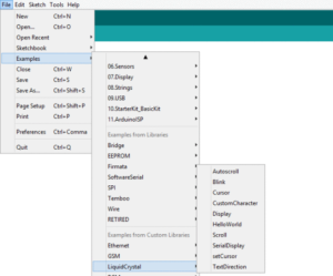
Writing code for Arduino is similar in nature to that of PSoC Creator. Once you create a new project, two methods are supplied by default which we need to implement namely setup() and loop(). The setup method needs to have the initialization of different components while the loop method need to have the application logic. The global variables can be defined at the top of the code.
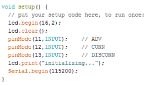
The following needs to be initialized
- LCD module
- The status pin: We need to mention the mode of the pins. In this case all three pins are input pins
- The Serial communication
The application logic is pretty straightforward. We read the value of three pins in the loop and write the data on LCD accordingly. If the CONN pin is ON then we will wait for the data from the serial port and when we read the data we will display it on the LCD shield
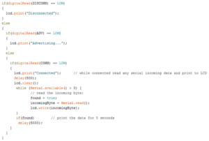
3. Pushing the code to Arduino: Once we have written the firmware code we can either compile the code to check for any errors (Verify option) or can directly push the code to Arduino (Upload option). Before we do that we must first connect the Arduino to the laptop/computer through a USB cable. After that verify that correct port and board are configured in Arduino IDE (under Tools -> Port and Tools -> Board)
Demo
[wpvideo RkX51Qwm]
Advantages
- Good documentation
- Plenty of example projects available
- The IDE comes with a rich set of tools for easy development, debugging and testing of the application being developed
Disadvantages
- IDE Specific to Cypress toolkit
- Hard to integrate with other open source platform (Unknown yet)
Next Steps
- Build upon the existing use case
- Identify some more use cases

